-
-
Notifications
You must be signed in to change notification settings - Fork 3.4k
New issue
Have a question about this project? Sign up for a free GitHub account to open an issue and contact its maintainers and the community.
By clicking “Sign up for GitHub”, you agree to our terms of service and privacy statement. We’ll occasionally send you account related emails.
Already on GitHub? Sign in to your account
Stroke cap+join support for WebGL #5802
Stroke cap+join support for WebGL #5802
Conversation
|
Amazing! A quick scan of this had me really excited. My capacity is very limited for the remainder of this month so I am unable to do a detailed review. @AdilRabbani would you want to take a look as an initial reviewer? I am remembering that you worked on some aspects of line/stroke rendering in the past. |
|
This is great! For the anti-aliasing, would it be possible to draw the alpha using a I believe in some circumstances discard can actually decrease performance as well, so it may be good to avoid it if we can. |
It would be, although the issue with this is that the semi-transparent pixels would still register in the depth buffer, so if after drawing one shape, I
Do you have any pointers for when this might be, at least so I can test the |
|
That's a good point about the depth testing, I don't have any experience with the order independent algorithms sadly. If you do a search for "discard performance glsl" you'll see a few things. I believe it can degrade performance if your depth test would otherwise ignore pixels being processed. It's definitely niche! |
|
Actually after playing around with your demo a bit, the anti-aliasing didn't bother me as much as I thought it would, so just ignore my previous comments! However, I did notice some strange shifting of the line widths, especially visible on the sphere when you zoom in closely. Any idea what might be causing that to happen? |
|
Thanks for this link! It sounds like WebGL won't be able to early-discard fragments behind lines. I guess if we wanted to optimize this, we could split line rendering into two passes: first all the straight segments using a fragment shader with no
I noticed this happening on v1.4.2 as well, so I wonder if it's because of this line that puts line vertices slightly above faces? I wonder if maybe, if you keep rotating a face, there's an angle at which that scale value isn't enough to keep the line on top of the face. |
Update on this! I did some reading, and have slightly more fully formed answers to the questions I raised.
Based on this:
References:
|
|
Updated now to support per-vertex stroke colors, added in #5915: There's a little bit of z fighting that can be noticed around joints when using really thick strokes with different colours on either side of the join, but I think that case is uncommon enough that we can address it separately. |
|
Thanks @davepagurek for working on it. I think this PR is ready to be merged if it looks good to you @stalgiag @aferriss. |
I think this is the correct diagnosis as you can't see this issue in I am personally good with this being merged. I wasn't able to do a detailed reading but I tested everything out and skimmed the changes. Everything looks great and I love the frag shader discard solution for the joins. I agree that a simplified shader could be an important addition down the road as I am seeing more people using p5 WebGL for mobile/VR work with a lot of geometry on screen simultaneously to the point where the caps/joins won't really be visible. Thanks so much for this @davepagurek ! |
|
Thanks @stalgiag! I'm going to merge this in for now and make an issue to track the stroke jittering issue, and another to discuss mobile performance and potential paths forward for that. |


Resolves #5790
Changes
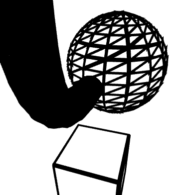
strokeCapandstrokeJoininp5.RendererGLScreenshots of the change:
Live demo here: https://editor.p5js.org/davepagurek/sketches/8SSUdaVhi
Explanation
Design goals
Design
To accomplish all this, I've chosen the following design:
aTangentIn=aTangentOut= the direction of the segmentaSideis either 1 or -1, indicating what side of the centerline it's onaTangentInis the tangent of the incoming segmentaTangentOutis the tangent of the outgoing segmentaSidewill be plus or minus 1, 2, or 3. The sign represents the side of the centerline; 1 indicates the vertex on the incoming side of the join; 2 is the elbow of the join; 3 is the outgoing sideaTangentInis the tangent going into the capaTangentOutis 0aSidewill be plus or minus 1 or 2, with 1 representing the side coming out of the segment, and 2 being the side projected out from the end of the segmentROUND:vCenter, the position of the centerline, is passed in from the vertex shader, and pixels greater than the radius away are discardedBEVEL: pixels are discarded if they are father along the normal from the center thanvMaxDist, a value provided by the vertex shader indicating the height of the bevelTradeoffs
Different default join mode
One thing to note is that MITER joins tend to look worse in WebGL mode than 2D mode. Whenever the join angle approaches 180 degrees, the stroke edges are so parallel that it takes a long distance for them to intersect into a join. This happens often with joins on the edge of 3D shapes, leading to little spikes being present:

I believe these will be unexpected to users and probably are not what they want at first. Because of this, I've opted to make
ROUNDjoints be the default in WebGL. This does introduce an inconsistency between modes, so let me know if you think this is reasonable or not!Antialiasing
Using

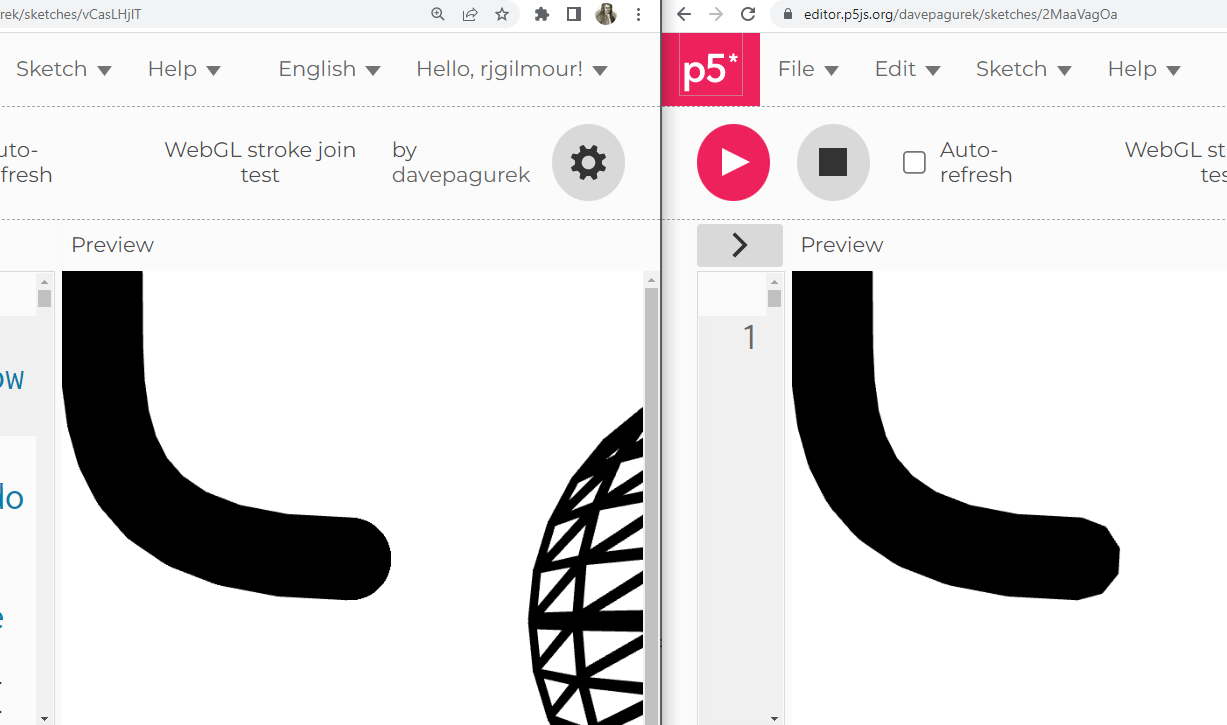
discardin the fragment shader does not seem to produce as good antialiasing compared to lines produced with actual geometry. I believe this tradeoff is still worthwhile, as we are trading slightly better antialiasing for fully rounded joins instead of polylines, and faster rendering due to significantly fewer vertices (we'd need a full circle of vertices in every join otherwise.) For what it's worth, a user on the p5 discord mentioned that they thought the shader version looked better than a prototype polyline version, providing this screenshot for comparison:Also, I'm using
discardand not changing the alpha in the fragment shader is because the transparent and semitransparent pixels would still be written to the depth buffer, occluding any subsequently drawn shapes that are supposed to be behind it, which would make a bit of a halo around the stroke.PR Checklist
npm run lintpasses